
Recently, the research results jointly completed by Lead Hydrogen Intelligent, a subsidiary of Lead Intelligent, and Shanghai Jiao Tong University were officially published in the international journal Fuel Cells (2026). This study first established a quantitative analysis method from equipment parameters to coating quality for the roll-to-roll narrow gap coating of fuel cell catalytic layers. It precisely quantified the impact mechanism and transmission rules of two types of equipment disturbances – coating die deformation and back roller runout – on wet film thickness. It proposed practical optimization paths such as the “balance sweet spot area” of gasket thickness and the stable coating window of back roller runout, and constructed a full-chain analysis framework of “equipment-process-product”, providing solid theoretical support for the mass production and consistency of catalytic layers.
In the batch manufacturing of fuel cell catalytic layers, the stability of equipment operation directly determines product consistency, commissioning efficiency, and line scaling capability. However, the core contradiction of a production line often hides in the transmission path of micro-meter-level deviations of equipment.
When low-speed commissioning, the film thickness is uniform and the state is stable. Once the speed increases and the width is increased, uneven thickness and longitudinal periodic fluctuations appear immediately. A few micrometers of coating die deformation or back roller runout, after being transmitted through the slurry flow field and coating liquid bridge, eventually amplify into noticeable wet film defects.
This is exactly the problem that is repeatedly encountered in mass production but difficult to answer: Why does the equipment precision meet the standards, yet the product performance remains unstable?
Recently, the latest research results jointly completed by Lead Hydrogen Intelligent and Shanghai Jiao Tong University were officially published in the internationally renowned journal Fuel Cells (2026) in the hydrogen energy field. This study first established a quantitative link from equipment parameters to coating quality for the roll-to-roll narrow gap coating of fuel cell catalytic layers. It precisely quantified the impact of coating die deformation and back roller runout on wet film thickness, providing solid theoretical support for the mass production and consistency of fuel cell catalytic layers.
Unpacking the black box of mass production
Quantitative tracking from “equipment disturbance” to “wet film quality”
The manufacturing of fuel cell catalytic layers is accelerating towards high-speed, continuous, and large-scale production. The higher the line speed and the wider the width, the more sensitive the final quality of the catalytic layer is to equipment disturbances. The same equipment may show completely different performance when using different slurries, increasing speed, or changing the film thickness requirements.
Traditional experience-based parameter tuning and single mechanical indicators are no longer sufficient to explain and predict product performance.
The real core problem is: How do small equipment deviations in high-speed coating convert through complex flow fields and coating liquid bridges into observable fluctuations in wet film thickness?
It’s like searching for the source of the “butterfly effect” in a high-speed running precision instrument.
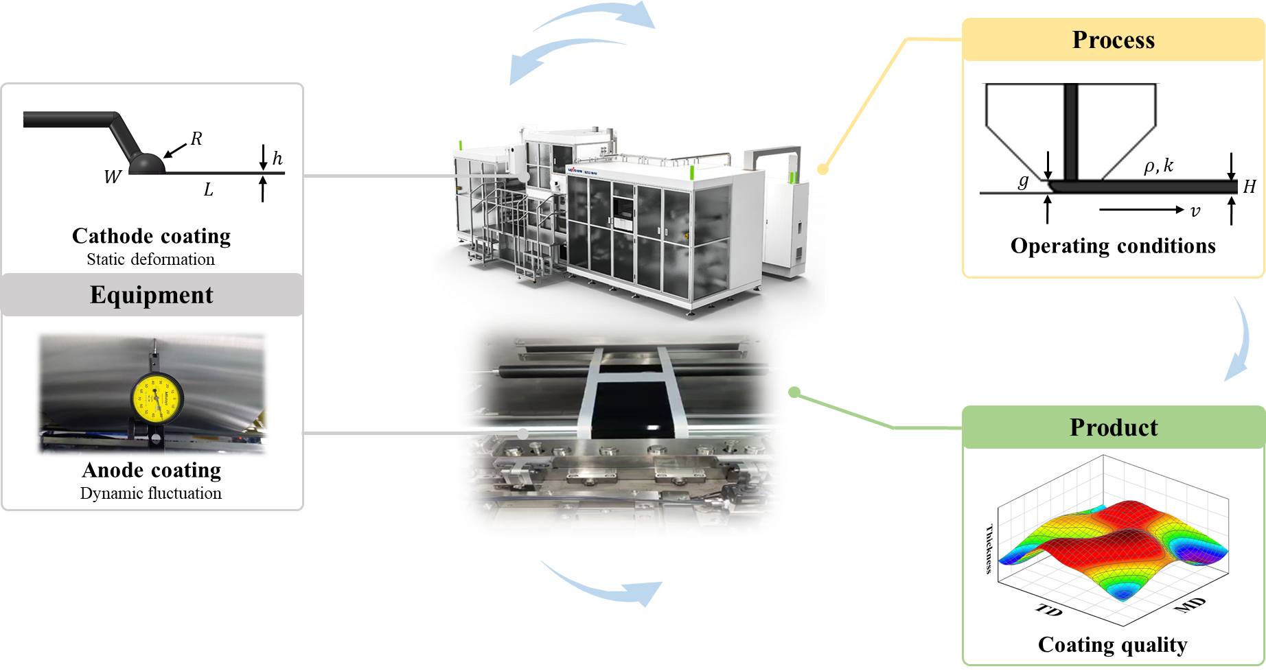
To unravel this mass production black box, the Lead Hydrogen Intelligent team proposed a new quantitative analysis method. Instead of viewing mechanical structures or process parameters in isolation, they tightly connect “equipment disturbance”, “process response”, and “final product quality”, clearly tracking and quantifying how actual disturbances in the equipment step by step affect the final wet film quality.
Two “invisible killers”
How to mess up your coating
The study deeply analyzed two typical equipment disturbance paths in high-speed coating processes, revealing their specific impacts on film thickness uniformity:
Coating die internal pressure-induced structural deformation (affects lateral TD uniformity)
During high-speed coating, the supply amount increases, leading to an increase in internal pressure of the coating die. The coating die is not absolutely rigid; under pressure, the middle of the die lip, which lacks structural constraints, is more easily stretched, while the sides have stronger constraints and smaller deformation, forming a “wider center and narrower edges” deformation trend.
This deformation changes the slit height and flow resistance at different positions along the lateral direction, increasing the outflow amount in the middle, ultimately resulting in a thicker central wet film and thinner sides. The higher the coating speed and the wider the coating die width, the more significant this deformation becomes.
Back roller radial runout-induced longitudinal fluctuation (affects longitudinal MD stability)
Back roller runout causes periodic changes in the coating gap, thereby affecting the liquid bridge pressure and meniscus position. The study detailed the influence rules of fluctuation amplitude, direction, period, and coating speed:
○ Gap reduction: The liquid bridge moves upstream, and when the fluctuation is too large, the slurry accumulates upstream, causing the subsequent wet film to first become thin, then recover, and even overshoot;
○ Gap increase: The liquid bridge moves downstream, and when it is too large, the stability of the liquid bridge decreases, and gas intrusion may occur;
○ The larger the fluctuation amplitude, the more obvious the wet film fluctuation, and once it exceeds the stable coating window, the disturbance impact quickly amplifies;
○ After speeding up, the liquid bridge is closer to the stable boundary, making it more sensitive to the same amplitude of back roller runout.
From mechanism analysis
to practical optimization paths
The value of this work is not only in explaining phenomena, but more importantly in establishing a set of reusable analysis methods: identifying key disturbance sources at the equipment level, analyzing how disturbances change flow fields and liquid bridge behaviors at the process level, and evaluating the impact on wet film uniformity and coating stability at the product level.
Based on this, the study provided two directions for practical optimization:
Lateral: Gasket thickness has a “sweet spot”
Increasing gasket thickness can reduce internal pressure and deformation of the coating die, but excessive thickness weakens the coating die’s ability to distribute lateral flow. Uniformity shows a three-interval characteristic with improvement followed by deterioration as the gasket thickens:
○ Deformation-dominated zone: Thin gasket, high pressure, deformation is the main issue;
○ Balanced zone: Suppresses deformation while retaining sufficient flow distribution capacity – optimal range;
○ Flow distribution limitation zone: Over-thick gasket, the inherent flow distribution issue of the coating die begins to dominate.
Note that the sensitivity of different width coating dies to structural deformation and flow distribution varies, so the suitable gasket range cannot be directly copied.
Longitudinal: Control back roller runout within the “stable coating window”
Back roller runout should not be judged solely based on a single mechanical indicator, but rather evaluated comprehensively considering the actual slurry, line speed, and nominal gap. The core principle is that the instantaneous gap caused by back roller runout should be kept within the stable coating window throughout the entire operating cycle.
After line speed-up, slurry change, or film thickness adjustment, the allowable gap fluctuation range must be re-evaluated – transforming equipment precision requirements into quality control indicators facing product quality.
It’s not just about “making the equipment”
It’s about “understanding the equipment”
The significance of this study goes beyond explaining two phenomena; it provides mechanistic support for the full lifecycle management of fuel cell catalytic layer equipment:
○ Design phase: Combining slurry properties, target film thickness, and operating speed, evaluate the impact of coating die structure and channel design on coating quality, identify potential risks earlier, and enhance design targeting.
○ Commissioning phase: When lateral non-uniformity or longitudinal fluctuations occur, through the “equipment-process-product” analysis chain, effectively distinguish whether the problem comes from coating die flow distribution, structural response, or back roller condition and gap dynamic changes, significantly shortening the commissioning cycle.
○ Operation phase: Link the operational status of key components such as back rollers and coating dies with actual coating results, upgrading traditional equipment maintenance to quality management oriented towards product consistency.
Lead Hydrogen Intelligent always believes that customers need not only “operational equipment” but also equipment capabilities that understand the mechanism of quality formation, support process optimization, and enable mass production scaling.
Around narrow gap coating, Lead Hydrogen Intelligent has established not only mechanical structures but also a quantitative analysis method from equipment parameters to coating quality – serving both equipment design and process scaling, problem diagnosis, and stable mass production.
From “experience-based parameter tuning” to “mechanism-driven”; from “single parameter compliance” to “full-chain quality controllability” – Lead Hydrogen Intelligent is breaking the consistency boundary of fuel cell catalytic layer mass production with deep equipment-level understanding.
Paper information: https://doi.org/10.1002/fuce.70123
Fuel Cells・2026・SCI
Unit: Shanghai Jiao Tong University・Lead Hydrogen Intelligent